HDL for synthesis · Lesson 2 of 4
Verilog and SystemVerilog for synthesis
Write synthesizable Verilog and SystemVerilog: modules, ports, parameters, logic, always_ff and always_comb, blocking vs non-blocking assignment and generate.
What you will learn
- Write a parameterised SystemVerilog module and instantiate it with named port connections
- Choose between always_ff, always_comb and continuous assignment for a piece of logic
- Apply the blocking and non-blocking assignment rules and explain what breaks when they are ignored
- Avoid sizing and signedness mistakes in vectors, literals and arithmetic
- Tell synthesizable constructs apart from simulation-only ones
Before you start
- What is an FPGA (lesson 1)
- The FPGA design flow (lesson 3)
- Basic digital logic: gates, flip-flops, binary numbers
After this lesson you can write synthesizable SystemVerilog modules, connect them into a hierarchy, and avoid the handful of mistakes that cause most beginner bugs: wrong assignment type, silent truncation and accidental unsigned arithmetic. The examples use SystemVerilog, which every current FPGA synthesis tool accepts for design code. Plain Verilog-2001 differences are listed at the end.
An HDL describes hardware, not a program
Verilog looks like C, but it does not run line by line on a processor. Each assign statement, each always block and each module instance describes a piece of hardware. All of that hardware exists at the same time and works in parallel.
Take these two lines:
assign sum   = a + b;
assign carry = a & b;
Swapping their order changes nothing. They describe an adder and an AND gate, side by side, both connected to a and b. Order only matters inside a procedural block, and even there it matters in a specific way that this lesson explains below.
A useful habit: before writing a line of HDL, sketch the registers and the logic between them. Then write code that describes that sketch. If you cannot say what hardware a line produces, the synthesis tool may produce something you did not expect.
Modules, ports and parameters
A module is the unit of hardware. It has ports (its pins) and an implementation. Here is a counter with a synchronous reset and a count enable:
module counter #(
    parameter int WIDTH = 8
) (
    input  logic             clk,
    input  logic             rst,    // synchronous, active high
    input  logic             en,     // count enable
    output logic [WIDTH-1:0] count
);

    always_ff @(posedge clk) begin
        if (rst)
            count <= '0;
        else if (en)
            count <= count + WIDTH'(1);
    end

endmodulecounter.sv
The parts:
#(parameter int WIDTH = 8)declares a parameter with a default value. Parameters are constants fixed at elaboration time. Use them for widths, depths and clock frequencies so one module serves many uses.- The port list uses ANSI style: direction, type and width in one place.
input,outputandinoutare the three directions. Reserveinoutfor the top-level pins that really are bidirectional. '0is SystemVerilog shorthand for “all bits zero” at whatever width the target has.'1sets all bits to one.WIDTH'(1)is a size cast. It makes the constant exactlyWIDTHbits so the addition has matching widths and lint tools stay quiet.
Instantiation with named port connections
To use a module, you instantiate it inside another module. This top level cascades two counters into a 12-bit count:
module counter_top (
    input  logic        clk,
    input  logic        rst,
    input  logic        en,
    output logic [11:0] count
);

    logic [3:0] low;
    logic [7:0] high;
    logic       low_wrap;

    // The low counter wraps when it is at 4'hF and about to count.
    assign low_wrap = en && (low == 4'hF);

    counter #(.WIDTH(4)) u_low (
        .clk   (clk),
        .rst   (rst),
        .en    (en),
        .count (low)
    );

    counter #(.WIDTH(8)) u_high (
        .clk   (clk),
        .rst   (rst),
        .en    (low_wrap),
        .count (high)
    );

    assign count = {high, low};

endmodulecounter_top.sv
#(.WIDTH(4)) overrides the parameter for that instance. u_low and u_high are instance names; they appear in the simulator hierarchy and in synthesis reports, so give them meaningful names. .port(signal) is a named connection. Always use named connections. Positional connections (counter u0 (clk, rst, en, low);) compile fine and break silently when someone reorders the ports.
SystemVerilog also accepts .clk as shorthand for .clk(clk) and .* to connect every port to a signal of the same name. .* saves typing but hides the connections from a reader. Explicit named connections are the safer default.
Nets and variables: wire, reg and logic
Verilog-2001 has two kinds of signal:
wireis a net. A continuousassignor a module output drives it.regis a variable. Analwaysorinitialblock assigns it.
The name reg misleads beginners. A reg assigned in a combinational always block is not a register; it is just a variable the synthesis tool turns into gates. Whether you get a flip-flop depends on how the block is written, not on the keyword.
SystemVerilog adds logic, which can be used in both places. A logic signal can be driven by one continuous assignment, or by procedural code, or connected to a module output. Use logic for almost everything. You still need a net type such as wire when a signal has more than one driver, which in FPGA design means a bidirectional top-level pin. The combinational logic lesson covers tri-states.
Vectors and literals
logic [7:0] data; declares an 8-bit vector with bit 7 as the most significant bit. Use [N-1:0] consistently; mixing [0:7] and [7:0] in one design invites bit-order bugs.
Literal syntax is <width>'<base><value>:
| Literal | Meaning |
|---|---|
8'hA5 | 8 bits, hex A5 |
4'b1010 | 4 bits, binary 1010 |
12'd100 | 12 bits, decimal 100 |
8'sd5 | 8 bits, signed decimal 5 |
100 | unsized decimal, at least 32 bits, signed |
'0, '1 | fill every bit of the target with 0 or 1 |
8'b1010_0101 | underscores are ignored and help readability |
Width mismatches do not cause errors. If you assign 8'hFF to a 4-bit signal, the upper bits are dropped. If you assign a 4-bit value to an 8-bit signal, it is zero-extended (or sign-extended if the value is signed). This is legal and often a bug. Run a linter: verilator --lint-only -Wall reports width mismatches as WIDTHTRUNC or WIDTHEXPAND warnings.
Concatenation {a, b} joins vectors, and replication {4{1'b1}} repeats one. {high, low} in counter_top builds the 12-bit result.
Signed arithmetic pitfalls
Vectors are unsigned unless declared signed. The rule that catches people: if any operand in an expression is unsigned, the whole expression is evaluated as unsigned.
logic signed [7:0] a = -8'sd5;   // bit pattern 8'hFB
logic        [7:0] b = 8'd2;     // unsigned
logic signed [7:0] c = 8'sd2;    // signed

// a < b          is false: compared as 251 < 2
// a < c          is true:  compared as -5 < 2
// a < $signed(b) is truetb_signed.sv
Three more cases produce an unsigned result even when the source is signed: a part-select such as a[7:0], a concatenation such as {a, 1'b0}, and any based literal written without the s marker, such as 8'd3. When you need signed arithmetic, declare every operand signed, or wrap operands in $signed(). Then check the result in simulation with negative inputs.
Continuous assignment
assign describes combinational logic that is always active:
assign y      = sel ? b : a;          // 2:1 multiplexer
assign parity = ^data;                // XOR of all bits
assign {cout, sum} = a + b;           // adder with carry out
Use assign for simple expressions. When the logic needs if or case, use always_comb.
always_ff, always_comb and always @*
Verilog-2001 has one procedural block, always, and the sensitivity list decides what it means. always @(posedge clk) describes flip-flops. always @* describes combinational logic. Nothing stops you from writing something in between that synthesizes to a latch or does not match simulation.
SystemVerilog adds three blocks that state your intent:
always_ff @(posedge clk)for flip-flops. Tools may warn if the body does not describe sequential logic.always_combfor combinational logic. It infers its own sensitivity list, runs once at time zero, and tools may warn when the code implies a latch.always_latchfor the rare case where you want a latch. In FPGA design you almost never do.
always_comb has two concrete advantages over always @*. It executes at time zero, so outputs start with values computed from the inputs instead of staying x until some input changes. It also forbids any other process from writing the same variables, which catches multiple-driver mistakes before simulation starts.
always_comb begin
    y = '0;              // default value on every path
    if (en)
        y[sel] = 1'b1;
end
The sequential logic lesson covers always_ff styles for resets and enables.
Blocking and non-blocking assignment
Inside a procedural block there are two assignment operators:
- Blocking
=updates the variable immediately. The next line sees the new value. - Non-blocking
<=evaluates the right-hand side now and schedules the update for the end of the time step. Every line in the block sees the old values.
Non-blocking assignment models what flip-flops do: on a clock edge every register samples its input at the same instant, then all outputs change together.
Worked example: a three-stage delay line
The correct version uses <=:
always_ff @(posedge clk) begin
    q1 <= d;
    q2 <= q1;
    q3 <= q2;
end
On each edge q1 takes d, q2 takes the old q1, and q3 takes the old q2. A pulse on d appears on q3 three clock edges later.
The following block is wrong. It is the same code with blocking assignments:
// WRONG: blocking assignments in a clocked block
always_ff @(posedge clk) begin
    q1 = d;
    q2 = q1;    // reads the q1 written one line above, which is d
    q3 = q2;    // reads the q2 written one line above, which is d
end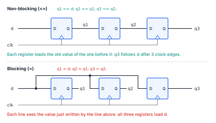
Every register now loads d on the same edge, as the lower half of the figure shows. The delay line has become a single register, and a synthesis tool may merge the three identical flip-flops into one. The testbench drives a one-cycle pulse into both versions:
edge 1: d_hist=0001 q3_good=0 q3_bad=1
edge 2: d_hist=0010 q3_good=0 q3_bad=0
edge 3: d_hist=0100 q3_good=1 q3_bad=0
edge 4: d_hist=1000 q3_good=0 q3_bad=0
edge 5: d_hist=0000 q3_good=0 q3_bad=0
PASS
q3_bad shows the pulse after one edge instead of three. Verilator catches the mistake before you simulate: verilator --lint-only -Wall delay3_bad.sv reports BLKSEQ (blocking assignment in sequential logic) on all three lines.
delay3.sv
Download delay3_bad.sv (wrong on purpose)
Download tb_verilog_basics.sv
Reversing the line order (q3 = q2; q2 = q1; q1 = d;) happens to give a working shift register with blocking assignments. Do not rely on that. The code then depends on statement order, and the next person to edit it will not know.
A second failure mode involves two blocks. If always @(posedge clk) a = b; and always @(posedge clk) b = a; are in separate blocks, the simulator may run either block first, and the result depends on that order. The hardware is two registers swapping values. Non-blocking assignment removes the race.
The rules
- In
always_ff, use only<=. - In
always_comb, use only=. - Never mix
=and<=in one block. - Assign each variable from exactly one block.
Follow these four rules and simulation matches hardware for the constructs in this course.
Generate blocks
Generate constructs create hardware at elaboration time, controlled by parameters. A generate for loop replicates logic; a generate if or case picks between alternatives.
module bit_reverse #(
    parameter int WIDTH      = 8,
    parameter bit REGISTERED = 1'b1
) (
    input  logic             clk,
    input  logic [WIDTH-1:0] din,
    output logic [WIDTH-1:0] dout
);

    logic [WIDTH-1:0] rev;

    for (genvar i = 0; i < WIDTH; i++) begin : g_rev
        assign rev[i] = din[WIDTH-1-i];
    end

    if (REGISTERED) begin : g_reg
        always_ff @(posedge clk) dout <= rev;
    end else begin : g_comb
        assign dout = rev;
    end

endmodulebit_reverse.sv
The loop variable is a genvar, which only exists during elaboration. Label every generate block (: g_rev). The label names the hierarchy, so the instance of bit 3 appears as g_rev[3] in the simulator and in synthesis reports. Since Verilog-2005 the generate and endgenerate keywords are optional; older code wraps these blocks in them.
A procedural for loop inside always_comb is also synthesizable when its bounds are constants. The tool unrolls it into parallel hardware. It is not a loop that runs over time.
Synthesizable and simulation-only constructs
The language has two audiences: synthesis tools and simulators. Much of it only makes sense to the simulator.
| Synthesizable | Simulation only (ignored or rejected by synthesis) |
|---|---|
module, ports, parameters, localparam | # delays such as #10 |
assign, always_ff, always_comb | $display, $monitor, $finish, $random |
if, case, operators, functions | fork/join, wait, force/release |
for loops with constant bounds | while loops with data-dependent exit |
Generate for, if, case | Classes, queues, dynamic arrays |
| Packed structs, enums, packages | File I/O (except memory initialisation, below) |
Two items sit on the border. initial blocks are simulation constructs in general, but FPGA tools accept initial values on registers and $readmemh/$readmemb for memory contents, because an SRAM-based FPGA loads every flip-flop and block RAM during configuration. The memory lesson uses this. Second, synthesis tools ignore # delays, often with only a warning. A design that only works in simulation because of a delay will fail in hardware.
Verilog-2001 compared with SystemVerilog
| Topic | Verilog-2001 | SystemVerilog (for design) |
|---|---|---|
| Signal types | wire, reg | logic for nearly everything |
| Flip-flop block | always @(posedge clk) | always_ff @(posedge clk) |
| Combinational block | always @* | always_comb |
| Fill literals | {WIDTH{1'b0}} | '0, '1 |
| Size casts | not available | WIDTH'(x), signed'(x) |
| Port connection shorthand | named or positional only | .clk, .* |
| User types | none | typedef, enum, struct packed |
| Shared definitions | `include files | package and import |
| Case checking | tool pragmas in comments | unique case, priority case |
The right-hand column is part of the synthesizable subset that FPGA vendors document. Support for individual constructs still differs between tools and versions, and the built-in SystemVerilog front end of the open-source Yosys flow covers a smaller subset. If a tool rejects a construct, check its synthesis guide.
Checking your code
Every design file in this lesson passes both of these commands with no warnings:
iverilog -g2012 -Wall -o /dev/null counter.sv
verilator --lint-only -Wall counter.sv
Two exceptions are deliberate. delay3_bad.sv triggers BLKSEQ, which is the point of the example. bit_reverse.sv with REGISTERED = 0 leaves clk unconnected internally, and Verilator reports UNUSEDSIGNAL. To run the testbench:
iverilog -g2012 -o sim tb_verilog_basics.sv counter.sv counter_top.sv \
    delay3.sv delay3_bad.sv bit_reverse.sv
vvp sim
Verilator’s -Wall is strict and catches width, signedness and assignment-type mistakes that Icarus accepts silently. Run it on every module you write. The testbenches lesson shows how to structure self-checking tests like the one above.
Write a parameterised register with enable
Write a module en_reg with a parameter WIDTH (default 16), inputs clk, rst (synchronous, active high), en and d[WIDTH-1:0], and output q[WIDTH-1:0]. On a rising edge, reset clears q; otherwise q loads d when en is high. Then instantiate two copies in a top module: one 16 bits wide and one 4 bits wide, using named port connections. Lint both files with verilator --lint-only -Wall.
Show solution
module en_reg #(
    parameter int WIDTH = 16
) (
    input  logic             clk,
    input  logic             rst,
    input  logic             en,
    input  logic [WIDTH-1:0] d,
    output logic [WIDTH-1:0] q
);

    always_ff @(posedge clk) begin
        if (rst)
            q <= '0;
        else if (en)
            q <= d;
    end

endmodule

module en_reg_top (
    input  logic        clk,
    input  logic        rst,
    input  logic        en,
    input  logic [15:0] d16,
    input  logic [3:0]  d4,
    output logic [15:0] q16,
    output logic [3:0]  q4
);

    en_reg u_wide (
        .clk (clk),
        .rst (rst),
        .en  (en),
        .d   (d16),
        .q   (q16)
    );

    en_reg #(.WIDTH(4)) u_narrow (
        .clk (clk),
        .rst (rst),
        .en  (en),
        .d   (d4),
        .q   (q4)
    );

endmodule
u_wide uses the default WIDTH of 16. Only <= appears in the always_ff block, and every port connection is named.
Find the bug
This block should compute y = (a + b) >> 1, the average of two 8-bit unsigned numbers, without losing the carry. It gives wrong results for large inputs. Explain why and fix it.
logic [7:0] a, b, y;
always_comb y = (a + b) >> 1;
Show solution
The expression width is set by the widest operand and the target, which are all 8 bits. The sum is computed in 8 bits, so the carry out of bit 7 is lost before the shift. For a = 200 and b = 100 the sum 300 wraps to 44 and y becomes 22 instead of 150. Make the sum 9 bits wide before shifting:
logic [8:0] sum9;
always_comb begin
    sum9 = {1'b0, a} + {1'b0, b};
    y    = sum9[8:1];
end
Summary
- HDL code describes hardware that runs in parallel. Sketch the registers and logic first, then write code that matches the sketch.
- Use
logic, ANSI port lists, parameters for widths, and named port connections on every instance. - Use
always_ffwith<=for registers andalways_combwith=for combinational logic. Never mix the two assignment types in one block. - Widths and signedness are silent sources of bugs. One unsigned operand makes the whole expression unsigned. Lint with
verilator -Wallto catch both. - Generate blocks build parameterised hardware at elaboration. Delays,
$displayand most of the verification language are for simulation only.
Check your understanding
Pick an answer for each question, then check. Answers stay hidden until you submit.
Further reading
- Documentation
- Documentation
- Documentation
- Documentation
- Tool
- Tool
Found a mistake or something unclear?Report a correction.
Follow this course
Get an email when new lessons and projects are added to this course.