Timing and clocks · Lesson 11 of 14
Clock domain crossing: synchronisers, Gray code, FIFOs
Move signals safely between FPGA clock domains: metastability and MTBF, two-flop synchronisers, pulse and handshake crossings, async FIFOs, resets, constraints.
What you will learn
- Explain metastability and how the MTBF of a synchroniser depends on resolution time
- Write a two-flop synchroniser, a toggle pulse synchroniser and a reset synchroniser in SystemVerilog
- Choose the right crossing for a single bit, a pulse, a counter or a multi-bit data word
- Describe how an asynchronous FIFO uses Gray-coded pointers to compute full and empty
- Constrain clock domain crossings in Vivado and Quartus without hiding real timing paths
Before you start
- Static timing analysis and timing closure (lesson 10)
- Sequential logic (lesson 7)
- Testbenches (lesson 9)
After this lesson you can move a bit, a pulse, a counter or a stream of data words from one clock domain to another without random failures. You will also be able to spot a crossing that passes simulation and timing analysis but will fail in the field.
A clock domain is the set of registers clocked by one clock. Two clocks from the same PLL with a fixed phase relation are related, and the timing analyser checks paths between them like any other path (timing analysis). This lesson covers asynchronous crossings: the clocks come from different oscillators, or their phase relation is unknown. A signal from an external pin with no clock, such as a push button, is also asynchronous.
Metastability
A flip-flop needs its input stable for the setup time before the clock edge and the hold time after it. With asynchronous clocks, the source changes at times unrelated to the destination clock. Sooner or later a change lands inside the setup-hold window. No constraint can prevent that, because the timing analyser cannot know when the edges align.
The storage element inside the flip-flop is a pair of cross-coupled inverters. It has two stable states and an unstable balance point between them, like a ball on top of a hill. A marginal input can leave it near that point. Noise and the feedback gain eventually push it to one side, but the time this takes has no fixed upper bound. Meanwhile the output can sit at an intermediate voltage, oscillate, or settle late, and the final value can be 0 or 1.
The probability that the latch is still undecided falls exponentially with time. That is what makes synchronisers work: give the flip-flop enough time to resolve before anything else uses its output.
MTBF
The mean time between synchroniser failures is usually written as:
- is the resolution time: how long the output of the first flop has to settle before the next flop samples it. For a two-flop synchroniser this is about one destination clock period, minus the clock-to-Q delay, the routing delay and the setup time of the second flop.
- is the resolution time constant of the flip-flop. It depends on the transistor technology and the circuit.
- is a device-dependent constant with units of time. It relates to the width of the window in which an input change causes metastability. and are measured by the silicon vendor; you do not choose them.
- is the destination clock frequency, and is the rate at which the asynchronous input changes.
The exponent dominates. Doubling halves the MTBF. Adding one more clock period of resolution time multiplies it by , which is a very large factor when is many times . That is why the fix for a weak synchroniser is almost always more resolution time: a third flop, a slower destination clock for the synchroniser, or keeping logic and long routes out of the synchroniser chain.
MTBF is per synchroniser, so a product with many synchronisers shipped in large numbers needs each one to be far better than the product target. Quartus can report MTBF estimates for the synchroniser chains it identifies.
The two-flop synchroniser
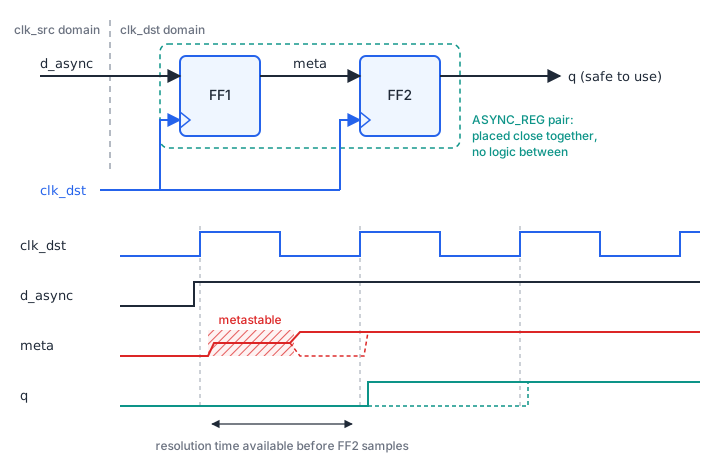
The basic crossing for a single bit is two flip-flops in series, both clocked by the destination clock. The first may go metastable. The second samples it one clock period later, after it has (almost certainly) resolved.
module sync_2ff #(
    parameter logic RESET_VALUE = 1'b0
) (
    input  logic clk,      // destination clock
    input  logic rst,      // synchronous reset, destination domain
    input  logic d_async,  // signal from another clock domain
    output logic q         // synchronised copy, two clk cycles later
);
    (* ASYNC_REG = "TRUE" *) logic sync_meta;   // first stage: may go metastable
    (* ASYNC_REG = "TRUE" *) logic sync_q;      // second stage: safe to use

    always_ff @(posedge clk) begin
        if (rst) begin
            sync_meta <= RESET_VALUE;
            sync_q    <= RESET_VALUE;
        end else begin
            sync_meta <= d_async;
            sync_q    <= sync_meta;
        end
    end

    assign q = sync_q;
endmodulesync_2ff.sv
Rules for the synchroniser itself:
-
No logic between the flops, and nothing else reads the first flop. Any logic eats resolution time.
-
The source must come straight from a register in the source domain. A combinational output can glitch, and the destination can catch a glitch as a real pulse.
-
Place the flops close together. In Vivado, the
ASYNC_REGattribute does this: it places the flops in the same slice where possible, stops optimisations such as shift-register extraction that would remove them, and tells the analysis tools these are synchronisers. -
In Quartus, mark the chain with the synchronizer identification setting so the Fitter keeps the flops together and the Timing Analyzer can report MTBF. In the
.qsffile:set_instance_assignment -name SYNCHRONIZER_IDENTIFICATION "FORCED IF ASYNCHRONOUS" -to "*sync_meta"The same setting can be written in HDL as
(* altera_attribute = "-name SYNCHRONIZER_IDENTIFICATION FORCED_IF_ASYNCHRONOUS" *).
The source signal must stay stable for longer than one destination period plus a margin, or the destination can miss it. For slow-changing levels (a mode bit, a status flag) that is easy. For short pulses it is not, which is the next section.
Crossing a pulse: the toggle synchroniser
A one-cycle pulse in a fast domain can be shorter than one period of the destination clock. The destination flop may never see it. The toggle synchroniser turns each pulse into a level change, synchronises the level, and turns each change back into a pulse.
// Source domain: each pulse flips the toggle.
always_ff @(posedge clk_src) begin
    if (rst_src) begin
        toggle_src <= 1'b0;
    end else if (pulse_src) begin
        toggle_src <= ~toggle_src;
    end
end

// Destination domain: two-flop synchroniser plus one flop for edge detection.
always_ff @(posedge clk_dst) begin
    if (rst_dst) begin
        sync_ff      <= 2'b00;
        toggle_dst_d <= 1'b0;
    end else begin
        sync_ff      <= {sync_ff[0], toggle_src};
        toggle_dst_d <= sync_ff[1];
    end
end

assign pulse_dst = sync_ff[1] ^ toggle_dst_d;
The limit: a second source pulse must not arrive before the destination has seen the first toggle. Otherwise the toggle flips back and both events can be lost. Keep at least three destination clock periods between source pulses (two synchroniser stages plus the edge-detect flop), and add margin. If the source cannot guarantee that spacing, use a handshake or a FIFO.
The testbench runs the clocks at 10 ns and 14.3 ns, sends 200 pulses with random spacing that obeys the rule, and checks that 200 one-cycle pulses come out. Remove the spacing and it reports failures.
Downloadpulse_sync.sv
Download tb_pulse_sync.sv
iverilog -g2012 -o sim tb_pulse_sync.sv pulse_sync.sv && vvp sim
# PASS: 200 pulses sent, 200 received
A simulation with ideal flip-flops never goes metastable, so a passing CDC testbench proves the protocol, not the synchroniser. Metastability is handled by the structure and checked by CDC analysis tools, covered at the end of this lesson.
Multi-bit values
Putting a two-flop synchroniser on every bit of a bus does not work. The bits travel on different routes with different delays, and each first-stage flop may or may not go metastable. When several bits change at once, the destination can capture some bits from the new value and some from the old. A counter going from 0111 to 1000 can be read as 1111, 0000 or any other mix. The destination sees a value the source never had.
There are three standard ways around this:
- Make only one bit change at a time: Gray code, for counters and pointers.
- Hold the data stable and send a single-bit control signal: a handshake.
- Use an asynchronous FIFO for a stream of data.
Gray code
In a Gray code, consecutive values differ in exactly one bit, including the wrap from the last value back to zero. If the destination samples while that one bit is changing, it reads either the old value or the new one. Both are valid counter values.
function automatic logic [N-1:0] bin2gray(input logic [N-1:0] b);
    return b ^ (b >> 1);
endfunction

function automatic logic [N-1:0] gray2bin(input logic [N-1:0] g);
    logic [N-1:0] b;
    b[N-1] = g[N-1];
    for (int i = N-2; i >= 0; i--) begin
        b[i] = b[i+1] ^ g[i];
    end
    return b;
endfunction
Three conditions must hold for a Gray-coded crossing:
- The Gray value must come from a register in the source domain, not from the output of
bin2graylogic, so it cannot glitch. - The value may only step by one (increment or decrement). Jumping from 3 to 7 changes several bits.
- The skew between the bits must be less than one source clock period, so one change has arrived everywhere before the next one starts. This is a constraint, shown below.
A standard (binary-reflected) Gray counter wraps with a one-bit change only when its length is a power of two, which is one reason FIFO depths are usually powers of two.
Handshake
For an arbitrary data word that changes rarely, such as a configuration value, hold the data stable and synchronise only a request and an acknowledge. A four-phase handshake works like this:
- The source drives the data and holds it. One cycle later it raises
req. - The destination synchronises
req. When it seesreqhigh, the data has been stable since beforereqrose, so it registers the data directly, without synchronisers, and raisesack. - The source synchronises
ackand lowersreq. It must not change the data before this point. - The destination sees
reqlow and lowersack. When the source seesacklow, it may send the next word.
The round trip takes several cycles in each domain, so a handshake suits low data rates. A two-phase variant uses the toggle idea: each change of req is one transfer, and each change of ack confirms it. The data bus needs a maximum-delay constraint so it arrives at the destination before the synchronised req does.
Vivado provides these crossings as Xilinx Parameterized Macros (XPM), such as xpm_cdc_single, xpm_cdc_gray, xpm_cdc_pulse and xpm_cdc_handshake, with their own constraints.
Asynchronous FIFOs
A FIFO with separate write and read clocks moves a stream of data between domains at full rate. The storage is a dual-port RAM: the write port uses the write clock, and the read port uses the read clock. A dual-clock block RAM does this directly. The only signals that cross domains are the two pointers.
- The write pointer lives in the write domain. It is kept in binary for addressing the RAM and in Gray code for the crossing.
- The read pointer lives in the read domain, with the same two forms.
- Each Gray pointer goes through a two-flop synchroniser (one per bit, which is safe because only one bit changes per step) into the other domain.
- Empty is computed in the read domain: the read pointer equals the synchronised write pointer.
- Full is computed in the write domain: the write pointer is one full lap ahead of the synchronised read pointer.
Like the synchronous FIFO in the memory and DSP lesson, the pointers carry one extra bit beyond the address so that full and empty can be told apart. In Gray code, “one lap ahead” means the top two bits differ from the synchronised read pointer and all the remaining bits are equal.
The synchronised pointer is always a few cycles old. That makes the flags pessimistic, never wrong. The read side may see “empty” for a few cycles after a word was written, and the write side may see “full” for a few cycles after a word was read. Neither causes an overflow or an underflow. The cost is that a FIFO needs a few extra entries of depth to sustain full throughput.
The details (flag registering, reset of both sides, almost-full thresholds) are easy to get wrong. Use the vendor FIFO (Vivado xpm_fifo_async or FIFO Generator, the Quartus dual-clock FIFO IP) unless you have a reason not to.
Reset synchronisers
An external reset is asynchronous to every internal clock. Asserting it asynchronously is fine: every flop goes to its reset state. Releasing it asynchronously is not. If the release lands near a clock edge, some flops leave reset on this edge and others on the next, and a state machine can start in an illegal state. The timing analyser checks this as recovery and removal timing, the reset equivalents of setup and hold, but only if the reset is synchronous to the clock.
The reset synchroniser asserts asynchronously and deasserts synchronously:
module reset_sync (
    input  logic clk,
    input  logic arst_n,     // asynchronous active-low reset
    output logic rst_n_out   // active-low reset for this clock domain
);
    (* ASYNC_REG = "TRUE" *) logic [1:0] rst_ff;

    always_ff @(posedge clk or negedge arst_n) begin
        if (!arst_n) begin
            rst_ff <= 2'b00;
        end else begin
            rst_ff <= {rst_ff[0], 1'b1};
        end
    end

    assign rst_n_out = rst_ff[1];
endmodulereset_sync.sv
When arst_n goes low, both flops clear at once and rst_n_out goes low with no clock needed. When arst_n goes high, the constant 1'b1 shifts through the two flops, and rst_n_out rises on a clock edge, two cycles later. The first flop can go metastable on the release, which is why there are two.
Each clock domain needs its own reset synchroniser. A PLL “locked” output is often ANDed into arst_n, so the domain stays in reset until its clock is stable.
Constraining crossings
Without constraints, the analyser times a crossing between unrelated clocks as if they were related, which gives meaningless results. Tell the tool what each crossing is.
Single-bit synchronisers and reset synchronisers. The path into the first flop has no meaningful requirement. Cut it, but only that path:
# Vivado: the first stage of every sync_2ff instance
set_false_path -to [get_cells -hierarchical -filter {NAME =~ */sync_meta_reg}]
Gray-coded buses and handshake data. The bus skew must stay below one source clock period. In Vivado, set_max_delay -datapath_only sets a limit on the data path delay and leaves out clock skew, which has no meaning between unrelated clocks:
# Vivado: Gray write pointer into the read-domain synchroniser, write clock 8 ns
set_max_delay -datapath_only 8.000 \
    -from [get_cells {wptr_gray_reg[*]}] \
    -to   [get_cells {wptr_gray_sync1_reg[*]}]
Whole clock pairs. set_clock_groups -asynchronous removes all timing between the groups:
set_clock_groups -asynchronous -group [get_clocks clk_a] -group [get_clocks clk_b]It is short, but it has a catch in Vivado: set_clock_groups has a higher priority than set_max_delay, so any max delay constraints on the same crossings are ignored. Use clock groups only when no crossing between the two clocks needs a bounded delay. For designs with Gray-coded or handshake buses, constrain each crossing explicitly instead.
Quartus reads the same set_false_path and set_clock_groups commands, with Quartus naming. It has no -datapath_only option. For bus crossings, the Quartus Timing Analyzer documentation describes set_net_delay and set_max_skew to keep the routes short and the bits aligned.
CDC checking tools
Timing analysis does not find a missing synchroniser; a structural CDC check does. Vivado has report_cdc, and Quartus includes CDC rules in its Design Assistant. Dedicated commercial CDC tools, such as Siemens Questa CDC and Synopsys SpyGlass CDC, go further and check protocols such as handshakes and Gray coding. Typical findings are a bus with per-bit synchronisers, logic between synchroniser flops, a combinational signal driving a crossing, and two synchronised signals that are later combined (reconvergence) and can disagree for a cycle. Run one of these checks on every design with more than one clock.
Pick the crossing
Choose a crossing method for each signal and say why.
- A
link_upstatus bit that changes a few times per second, from a 125 MHz Ethernet domain to a 100 MHz system domain. - A one-cycle
frame_startpulse from a 148.5 MHz video domain to a 25 MHz control domain. Frames start about 60 times per second. - A 32-bit gain value written by a CPU in a 50 MHz domain and used by a 200 MHz DSP pipeline. It changes a few times per second.
- A 16-bit ADC sample stream at 10 million samples per second, from the 80 MHz ADC clock to a 100 MHz processing clock.
- A free-running 10-bit write counter that the other domain must read to know how many words are available.
Show solution
- Two-flop synchroniser. It is a single-bit level that stays stable for much longer than a destination period.
- Toggle pulse synchroniser. The pulse is shorter than one 25 MHz period, so a plain synchroniser can miss it. The pulses are far apart (about 16.7 ms), far more than three destination cycles.
- Handshake (or a vendor CDC macro such as
xpm_cdc_handshake). The word is wide and changes rarely, so hold it stable and synchronise a request and acknowledge. Per-bit synchronisers would let the DSP pipeline see a mix of old and new bits. - Asynchronous FIFO. The data rate is continuous, and the FIFO also absorbs the rate difference between the domains.
- Gray-code the counter in a register in the source domain, synchronise each bit with two flops, and convert back to binary in the destination. Constrain the bus with
set_max_delay -datapath_only(Vivado) orset_net_delayandset_max_skew(Quartus).
Find the bug
This code moves a busy flag from the clk_a domain to clk_b. It passes simulation. Find the problem.
// clk_a domain
assign busy = (state != IDLE) && fifo_not_empty;

// clk_b domain
always_ff @(posedge clk_b) begin
    busy_meta <= busy;
    busy_sync <= busy_meta;
end
Show solution
busy is combinational. When state and fifo_not_empty change on the same clk_a edge, the AND gate can glitch for a short time. clk_b may sample the glitch and see a pulse that never existed in the clk_a design. Register busy in the clk_a domain first and synchronise the register output. Also add (* ASYNC_REG = "TRUE" *) (or the Quartus equivalent) on busy_meta and busy_sync, so the tools keep them together and recognise them as a synchroniser.
Summary
- Asynchronous inputs will eventually violate setup or hold at the destination flop. The flop can go metastable, and the time to resolve falls off exponentially, so MTBF grows exponentially with the resolution time .
- A single bit crosses through two flops in the destination domain, with no logic between them, a registered source, and
ASYNC_REG(Vivado) or synchronizer identification (Quartus). - Short pulses cross as a toggle; counters cross in Gray code; rarely changing words cross with a handshake; data streams cross through an asynchronous FIFO with Gray-coded pointers.
- Each clock domain needs its own reset synchroniser: assert asynchronously, release synchronously.
- Constrain every crossing: false paths into single-bit synchronisers,
set_max_delay -datapath_only(orset_net_delayandset_max_skewin Quartus) on buses, and clock groups only where no bus needs a bounded delay. Then run a CDC check.
Check your understanding
Pick an answer for each question, then check. Answers stay hidden until you submit.
Further reading
- Paper
- Documentation
- Documentation
Found a mistake or something unclear?Report a correction.
Follow this course
Get an email when new lessons and projects are added to this course.