HDL for synthesis · Lesson 8 of 14
Finite state machines in SystemVerilog
Design Moore and Mealy state machines in SystemVerilog: enum states, two-process and one-process style, registered outputs, encoding and safe FSMs.
What you will learn
- Explain the difference in output timing between a Moore and a Mealy machine
- Turn a state diagram into a two-process SystemVerilog FSM with an enum state type
- Register FSM outputs without adding a cycle of latency
- Choose a state encoding or leave the choice to the synthesis tool
- Make an FSM recover from illegal states and know where synthesis can undo that
Before you start
- Verilog and SystemVerilog for synthesis (lesson 4)
- Combinational logic (lesson 6)
- Sequential logic (lesson 7)
After this lesson you can turn a state diagram into a SystemVerilog state machine that synthesises cleanly, has glitch-free outputs and recovers from illegal states. The worked example is a sequence detector, verified against a reference model in a self-checking testbench.
What a state machine is made of
A finite state machine (FSM) is sequential logic with a small, named set of states. Every FSM has three parts:
- A state register: a group of flip-flops that holds the current state.
- Next-state logic: combinational logic that computes the next state from the current state and the inputs.
- Output logic: logic that computes the outputs.
Strictly, every counter is an FSM. The term is used for logic whose behaviour is easier to describe with named states than with arithmetic. A UART receiver (lesson 13) is a typical case: idle, start bit, data bits, stop bit.
Moore and Mealy machines
The two classic FSM types differ only in what the outputs depend on.
| Moore | Mealy | |
|---|---|---|
| Outputs depend on | Current state only | Current state and current inputs |
| Output timing | Changes after the clock edge that enters the state | Can change as soon as an input changes |
| States needed | Often one or two more | Often fewer |
| Combinational path from input to output | No | Yes |
The Mealy machine reacts one cycle earlier. The price is a combinational path from the inputs to the outputs. If the inputs glitch, the outputs glitch. If the output drives another FSM’s input, the two blocks of logic chain together and the timing path gets longer.
In FPGA design the usual choice is a Moore or Mealy machine whose outputs are registered, so they come straight from flip-flops. Use an unregistered Mealy output only when the extra cycle of latency matters and you have checked the timing.
The worked example: a 1011 sequence detector
The detector watches a serial input din, one bit per clock, and raises detect for one cycle every time the last four bits were 1011. Matches may overlap: the input 1011011 contains two matches, because the final 1 of the first match is also the first 1 of the next.
The states record how much of the pattern has been seen:
S_IDLE: no useful prefix.S_1: the last bit was1.S_10: the last bits were10.S_101: the last bits were101.S_1011: the whole pattern. This is the only state withdetect = 1.
For each state and input bit, the next state is the longest suffix of the bits seen so far that is also a prefix of 1011. For example, in S_101 an input of 0 gives 1010. The longest suffix of that which starts the pattern is 10, so the next state is S_10, not S_IDLE. Getting these back-arcs wrong is the most common bug in sequence detectors.
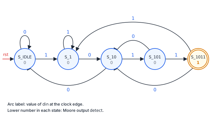
The same information as a state table:
| State | din = 0 | din = 1 | detect |
|---|---|---|---|
S_IDLE | S_IDLE | S_1 | 0 |
S_1 | S_10 | S_1 | 0 |
S_10 | S_IDLE | S_101 | 0 |
S_101 | S_10 | S_1011 | 0 |
S_1011 | S_10 | S_1 | 1 |
Write the table before the code. Each row becomes one line of the case statement.
Enum state types
SystemVerilog lets you declare the states as an enumerated type:
typedef enum logic [2:0] {
    S_IDLE = 3'd0,
    S_1    = 3'd1,
    S_10   = 3'd2,
    S_101  = 3'd3,
    S_1011 = 3'd4
} state_t;

state_t state, state_next;
This has two advantages over a list of localparam constants. The compiler rejects an assignment of a plain integer to a state_t variable unless you cast it, which catches typos and mixed-up state variables. In a testbench, state.name() returns the state name as a string, so $display("%s", state.name()) prints S_10 instead of 2. You can also leave out the values and let the tool number the states.
One portability note: Icarus Verilog 13 rejects state_next = din ? S_1 : S_IDLE; and asks for an explicit cast, while Verilator accepts it. An if/else works in both, so the code in this lesson uses that form.
The two-process style
The two-process style puts the state register in one always_ff block and the next-state logic in one always_comb block. The style is common, it keeps the transitions in one readable place, and synthesis tools recognise it as an FSM.
// Process 1: state register
always_ff @(posedge clk) begin
    if (rst) state <= S_IDLE;
    else     state <= state_next;
end

// Process 2: next-state logic (pure combinational)
always_comb begin
    state_next = state;               // default: stay
    case (state)
        S_IDLE: if (din) state_next = S_1; else state_next = S_IDLE;
        S_1:    if (din) state_next = S_1; else state_next = S_10;
        S_10:   if (din) state_next = S_101; else state_next = S_IDLE;
        S_101:  if (din) state_next = S_1011; else state_next = S_10;
        S_1011: if (din) state_next = S_1; else state_next = S_10;
        default: state_next = S_IDLE;     // recover from unused codes
    endcase
end
Three details matter:
- The default assignment
state_next = state;at the top ofalways_comb. Every path through the block now assignsstate_next, so no latch can be inferred, even if you later add a state and forget one branch. - The
defaultbranch of thecase. Three of the eight codes of a 3-bit register are unused. In simulation, the default branch sends an unknown or corrupted state back toS_IDLE. In hardware it may or may not survive synthesis; the section on safe FSMs explains why. - Only the state register has a reset. The next-state logic is combinational and needs none.
Keep datapath logic such as counters and data registers out of the next-state block. Put it in its own always_ff blocks, controlled by the state.
Registered outputs
The simplest Moore output is a decode of the state:
assign detect = (state == S_1011);That is correct, but detect is now the output of a LUT. When the state register changes, its bits do not all change at exactly the same time, and the decode can produce a short pulse that is not in the RTL. Inside a fully synchronous design that does not matter: the glitch is over before the next clock edge, and timing analysis checks that. It matters when the output leaves the clock domain: an FPGA pin, an asynchronous reset, a clock enable for another clock, or a signal sampled by another clock domain.
The fix is to register the output. Registering (state == S_1011) would delay detect by one cycle. Decoding state_next instead gives the same timing as the combinational decode, but from a flip-flop:
// Registered Moore output: decode the next state, store it in a flop.
always_ff @(posedge clk) begin
    if (rst) detect <= 1'b0;
    else     detect <= (state_next == S_1011);
end
This is called look-ahead output decoding. The cost is one flip-flop per output. FPGA logic cells pair each LUT with a flip-flop, so this costs very little.
Download the complete Moore detector:
Downloadseq_detect_moore.sv
The one-process style
The one-process style writes state and outputs in a single clocked block:
always_ff @(posedge clk) begin
    if (rst) begin
        state  <= S_IDLE;
        detect <= 1'b0;
    end else begin
        detect <= 1'b0;                        // default
        case (state)
            S_IDLE: if (din) state <= S_1; else state <= S_IDLE;
            S_1:    if (din) state <= S_1; else state <= S_10;
            S_10:   if (din) state <= S_101; else state <= S_IDLE;
            S_101:
                if (din) begin
                    state  <= S_1011;
                    detect <= 1'b1;            // entering the output state
                end else begin
                    state  <= S_10;
                end
            S_1011: if (din) state <= S_1; else state <= S_10;
            default: state <= S_IDLE;
        endcase
    end
end
Every output is registered automatically, and there is no always_comb block in which to create a latch. The catch is visible in the S_101 branch: because detect is a register, it has to be set on the transition into S_1011, not while the machine is in S_1011. You set outputs for the next state while reading the code for the current one. In large machines this causes off-by-one-cycle bugs.
The testbench below checks that both styles behave identically. Pick one style per project and use it consistently. A common compromise is the two-process style for the transitions plus separate always_ff blocks for registered outputs, as in seq_detect_moore.sv.
seq_detect_1p.sv
The Mealy version
A Mealy detector needs only four states, because the output does not need its own state. In S_101 with din = 1 the pattern is complete, so the output goes high in that cycle and the machine moves on to S_1:
always_comb begin
    state_next = state;
    detect     = 1'b0;
    case (state)
        S_IDLE: if (din) state_next = S_1; else state_next = S_IDLE;
        S_1:    if (din) state_next = S_1; else state_next = S_10;
        S_10:   if (din) state_next = S_101; else state_next = S_IDLE;
        S_101: begin
            if (din) begin
                detect     = 1'b1;   // pattern complete on this input
                state_next = S_1;    // the final 1 starts a new prefix
            end else begin
                state_next = S_10;
            end
        end
        default: state_next = S_IDLE;
    endcase
end
Note that detect also gets a default value at the top of the block, for the same reason as state_next.
The Mealy detect is high while the fourth bit is on din, before the clock edge that samples it. The Moore detect is high in the cycle after that edge. Registering the Mealy output gives the Moore timing back.
seq_detect_mealy.sv
State encoding
The state register stores a code for each state. The common encodings for a machine with N states are:
| Encoding | Flip-flops | Codes for 5 states | Notes |
|---|---|---|---|
| Binary (sequential) | ceil(log2 N) | 000, 001, 010, 011, 100 | Fewest flip-flops, more decode logic |
| Gray | ceil(log2 N) | 000, 001, 011, 010, 110 | One bit changes between consecutive codes |
| One-hot | N | 00001, 00010, 00100, 01000, 10000 | One flip-flop per state, simple next-state logic |
One-hot suits FPGAs well. Flip-flops are plentiful, and each next-state bit depends on only a few other state bits, so it fits in one or two LUTs. Binary uses fewer flip-flops but needs wider decode logic, which can add logic levels on the critical path. Gray encoding only helps when the machine mostly steps through states in a fixed order, as in a counter.
You rarely need to choose by hand. Synthesis tools recognise FSMs written in the two-process style and pick an encoding:
- AMD Vivado extracts FSMs and chooses an encoding automatically. The
fsm_encodingattribute on the state register overrides that; UG901 lists the valuesone_hot,sequential,johnson,gray,user_encodingandnone. The-fsm_extractionsynthesis option controls this globally. - Intel Quartus Prime accepts the
syn_encodingattribute with values such as"one-hot","sequential","gray","johnson","compact"and"user". - Yosys: the
fsmpass detects FSMs and re-encodes them as one-hot unless told not to. Setting(* fsm_encoding = "none" *)on the state register excludes it from FSM processing.
(* fsm_encoding = "one_hot" *) state_t state; // Vivado syntaxWrite clear code, leave the encoding to the tool, and read the synthesis log, which lists the state machines the tool recognised and the encoding it used. If your FSM is missing from that list, the tool did not recognise it. A common reason is a state register mixed up with datapath logic in the same block.
Safe state machines and illegal states
A 3-bit binary register for five states has three unused codes. A 5-bit one-hot register has 32 codes, of which 27 are illegal. An FSM in an illegal state may never leave it. Typical causes:
- An asynchronous input that feeds the next-state logic directly. Different state bits can sample it on opposite sides of a change and land on a code that no transition leads to. Synchronise external inputs first; lesson 11 on clock domain crossing covers how.
- A timing violation, which has the same effect. Lesson 10 on timing analysis covers how to find them.
- A single-event upset, where a particle strike flips a configuration or register bit. This matters for space, avionics and some industrial designs.
- A reset that is released asynchronously to the clock, so some flip-flops leave reset one cycle before others.
The first defence is the default branch shown earlier. The problem is that synthesis may remove it. From the tool’s point of view the unused codes are unreachable, so the logic that handles them never runs and can be optimised away. When the tool re-encodes the machine, for example from binary to one-hot, the codes that your default branch referred to no longer exist at all. The Quartus documentation states this directly: you cannot specify manual recovery logic for an FSM it extracts, because it eliminates that logic during optimisation.
To keep recovery logic, ask the tool for it:
- Vivado: put the
fsm_safe_stateattribute on the state register. UG901 lists the valuesreset_stateandpower_on_state(go to that state when an illegal state is detected),default_state(go to the state named in thedefaultbranch) andauto_safe_state(Hamming-3 encoding that corrects a single flipped bit). - Quartus: set
syn_encoding = "safe"on the state register. The tool adds logic that forces the machine to its reset state from any illegal state. The value can be combined with an encoding, for example"safe, one-hot". - Vivado or Yosys without a safe option: turn off FSM extraction for that register with
fsm_encoding = "none". The tool then treats thecasestatement as ordinary logic instead of re-encoding it, so thedefaultbranch is implemented like any other branch. Check the synthesised netlist to confirm.
(* fsm_safe_state = "reset_state" *) state_t state;   // Vivado
(* syn_encoding = "safe" *)          state_t state;   // Quartus
Safe FSMs cost logic and can lower Fmax, because every state now has extra decode logic. Use them where a stuck machine is a real risk: control FSMs that see external inputs, safety-related logic, and designs exposed to radiation. For an ordinary FSM fed by synchronised inputs and closed timing, a clean reset and the default branch are enough.
Testing the detectors
The testbench drives all three detectors with the same input and compares each output with a reference model. The model is a 4-bit shift register of the last bits clocked in: a match is simply hist == 4'b1011. That is a completely different implementation from the FSM, which is what makes it a useful check. If both were written as FSMs, the same misunderstanding of the back-arcs could end up in both.
// Reference model: the last four bits that were clocked in.
logic [3:0] hist;
always_ff @(posedge clk) begin
    if (rst) hist <= 4'b0000;
    else     hist <= {hist[2:0], din};
end
The checker runs on the falling clock edge, when every signal is stable. The Moore outputs must equal hist == 4'b1011. The Mealy output must equal {hist[2:0], din} == 4'b1011, because it already sees the bit on din. That difference in the two expressions is the one-cycle Moore/Mealy difference, written as code.
The stimulus is a few directed sequences (a single match, two overlapping matches, near misses) followed by 2000 random bits from $random with a fixed seed. Run it with Icarus Verilog:
iverilog -g2012 -o sim tb_seq_detect.sv seq_detect_moore.sv seq_detect_mealy.sv seq_detect_1p.sv
vvp sim
Expected output:
PASS: 138 matches seen, 0 errors
tb_seq_detect.sv:89: $finish called at 20275000 (1ps)
All four files also pass verilator --lint-only -Wall. A Verilator run reports a different match count with 0 errors, because its random generator gives a different sequence for the same seed. To see the testbench fail, change the S_101 row in seq_detect_moore.sv so that din = 0 goes to S_IDLE. Lesson 9 on testbenches explains each part of a testbench like this one.
tb_seq_detect.sv
Detect 1101 instead
Write a Moore detector for the pattern 1101, with overlapping matches, in the two-process style with a registered output. Start with the state table. Then change the reference model in the testbench to hist == 4'b1101 and check your design.
Hint: work out the back-arcs carefully. What is the longest suffix of 11011 that is also a prefix of 1101?
Show solution
The states are S_IDLE, S_1, S_11, S_110 and S_1101.
| State | din = 0 | din = 1 | detect |
|---|---|---|---|
S_IDLE | S_IDLE | S_1 | 0 |
S_1 | S_IDLE | S_11 | 0 |
S_11 | S_110 | S_11 | 0 |
S_110 | S_IDLE | S_1101 | 0 |
S_1101 | S_IDLE | S_11 | 1 |
Two arcs need care. From S_11, a further 1 gives 111, whose longest useful suffix is 11, so the machine stays in S_11. From S_1101, a 1 gives 11011, which ends in 11, so the next state is S_11. A 0 gives 11010, and none of its suffixes (1010, 010, 10, 0) starts 1101, so the next state is S_IDLE.
`timescale 1ns / 1ps

module seq_detect_1101 (
    input  logic clk,
    input  logic rst,
    input  logic din,
    output logic detect
);

    typedef enum logic [2:0] {
        S_IDLE, S_1, S_11, S_110, S_1101
    } state_t;

    state_t state, state_next;

    always_ff @(posedge clk) begin
        if (rst) state <= S_IDLE;
        else     state <= state_next;
    end

    always_comb begin
        state_next = state;
        case (state)
            S_IDLE: if (din) state_next = S_1;    else state_next = S_IDLE;
            S_1:    if (din) state_next = S_11;   else state_next = S_IDLE;
            S_11:   if (din) state_next = S_11;   else state_next = S_110;
            S_110:  if (din) state_next = S_1101; else state_next = S_IDLE;
            S_1101: if (din) state_next = S_11;   else state_next = S_IDLE;
            default: state_next = S_IDLE;
        endcase
    end

    always_ff @(posedge clk) begin
        if (rst) detect <= 1'b0;
        else     detect <= (state_next == S_1101);
    end

endmodule
This module passes iverilog -g2012 -Wall and verilator --lint-only -Wall, and matches a shift-register model over 3000 random bits.
Count the illegal states
A control FSM has 9 states. For binary and for one-hot encoding, give the number of state flip-flops, the number of legal codes and the number of illegal codes.
Show solution
- Binary: ceil(log2 9) = 4 flip-flops, 16 codes, 9 legal, 7 illegal.
- One-hot: 9 flip-flops, 2^9 = 512 codes, 9 legal, 503 illegal.
One-hot has far more illegal codes, but each legal code is easy to check: exactly one bit is set. Vivado’s auto_safe_state and Quartus’s safe mode add the detection logic for you.
Summary
- An FSM is a state register, next-state logic and output logic. Moore outputs depend only on the state; Mealy outputs also depend on the inputs and react one cycle earlier.
- Write the state table first, declare the states as a SystemVerilog
enum, and givestate_nextand every combinational output a default value at the top ofalways_comb. - Register outputs that leave the synchronous design. Decoding
state_nextinto a flip-flop gives a glitch-free output with no extra latency. - Let the synthesis tool choose the encoding and check its FSM report. One-hot is a good default on FPGAs.
- A
defaultbranch alone does not make an FSM safe, because synthesis may remove it. Usefsm_safe_statein Vivado orsyn_encoding = "safe"in Quartus where recovery matters, and synchronise inputs so illegal states do not occur in the first place.
Check your understanding
Pick an answer for each question, then check. Answers stay hidden until you submit.
Further reading
- Standard
- Documentation
- Documentation
- Tool
Found a mistake or something unclear?Report a correction.
Follow this course
Get an email when new lessons and projects are added to this course.